(Ⅲ) Motion Capture Case Study
This article uses the VRPN protocol as an example to systematically explain the data transmission implementation method between this motion capture system and the PX4 platform: first establish a real-time communication link through the VRPN protocol, then use the MAVLink message interface built into the PX4 platform to complete pose data parsing and fusion, and finally achieve high-frequency synchronization of drone motion state. Experimental verification shows that this method can stably transmit six-degree-of-freedom pose information, providing precise spatial positioning data support for research such as drone formation control and trajectory planning.
Ⅰ. Hardware Preparation
(Ⅰ) Prepare Drone
The drone platform used in this experiment uses the Pixhawk 2.4.8 flight control system as the core control unit. This flight controller is equipped with a dual-processor architecture (STM32F427 main controller and STM32F103 coprocessor), integrates a nine-axis MEMS sensor group such as L3GD20 gyroscope and LSM303D accelerometer, and supports MAVLink communication protocol. The flight control platform establishes a data link with the Raspberry Pi 3B onboard computer through UART serial port. This embedded system is equipped with a Broadcom BCM2837B0 quad-core processor (Cortex-A53 architecture, 1.4GHz main frequency), and is equipped with a carbon fiber ring protection frame to improve structural stability.
.png)
Drone Assembly
(Ⅱ) Network Topology
- Motion capture host (responsible for connecting motion capture cameras, fixed IP 10.1.1.198)
- Wireless router
- Raspberry Pi host
- Linux server (for running ground station software)
These devices will be connected to the same wireless router, and they can communicate with each other.
The network architecture of this experiment adopts a centralized topology design. All terminal devices are physically connected to the core switch through wireless access points (AP). At the data link layer level, these devices build a unified Layer 2 network architecture based on the IEEE 802.11 protocol family, achieving bidirectional data interaction capabilities across platform terminals.
In the current network configuration, the wireless router and gigabit Ethernet switch are logically integrated through OSI Layer 2 network bridging technology, forming a single broadcast domain network environment. This design brings heterogeneous devices such as drone systems and motion capture workstations into the 10.1.1.0/24 logical subnet.
.png)
Network Topology
Ⅱ. Installation and Configuration
(Ⅰ) Calibration and Marker Placement
The preparation work before data collection includes calibration and marker placement. For specific method tutorials, you can follow the technical articles - online training section of the NOKOV Motion Capture Service account.
.png)
Motion Capture System Calibration
When calibrating, note that the calibration axis of the motion capture software needs to have the z-axis upward. In our XINGYING software, the long axis is the x-axis, that is, the one with three points horizontally on the right is the x-axis, and the other side is the y-axis. When placing the drone, the drone's nose needs to face the positive direction of the x-axis.
.png)
Motion Capture System Calibration
(Ⅱ) Create Rigid Body
We used 12 motion capture cameras in this experiment.
.png)
Motion Capture Site
Create a rigid body in the scene.
For the specific process of creating a rigid body, you can also refer to the video explanation in the NOKOV Motion Capture Service account.
.png)
Rigid Body
(Ⅲ) VRPN Installation and Configuration
We performed data transmission through VRPN in this experiment. vrpn_client_ros needs to be configured and installed on the onboard computer.
.png)
vrpn_client_ros
(Ⅳ) PX4 Motion Capture Data Acquisition Method
- VRPN Method
.png)
Operation Steps
Specific operation methods:
- First use vrpn_client_ros on the Raspberry Pi to connect to the new host;
- Then start MavRos;
- Connect the Raspberry Pi to the flight controller;
- Topic forwarding, receive the topic about Tracker1 from VRPN, and forward it to the MavRos topic;
- On a remote host, whether it is a motion capture computer or a separate high-performance server, start the ground station on it to control the drone and view its status information.
- MOCAP Method
.png)
Operation Steps
The second method is to not use VRPN, but directly use the NOKOV customized software package, named MOCAP_NOKOV. Wikipedia has software introduction, and the corresponding code repository can be obtained on GitHub.
If your current system does not support direct installation, you can consider downloading the source code and compiling it locally for use.
The subsequent steps are the same as the method. The main difference is in the topic forwarding link, where the corresponding topics will change.
(Ⅴ) Multi-Host Communication Configuration
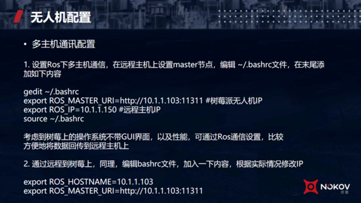
Multi-Host Communication Configuration
We usually use clusters, so there will be multiple ROS hosts. Here is an introduction to multi-host communication.
Our local environment is as follows:
- An onboard computer, set it as the master node
- An Ubuntu server
- A Raspberry Pi
Because we mainly consider that the operating system on the Raspberry Pi has relatively tight resources and no graphical interface. So the Master's URI is positioned to the Raspberry Pi's IP. Mainly use ROS to transmit data back to the remote host.
Similarly, content needs to be added to the bashrc file on the Raspberry Pi.
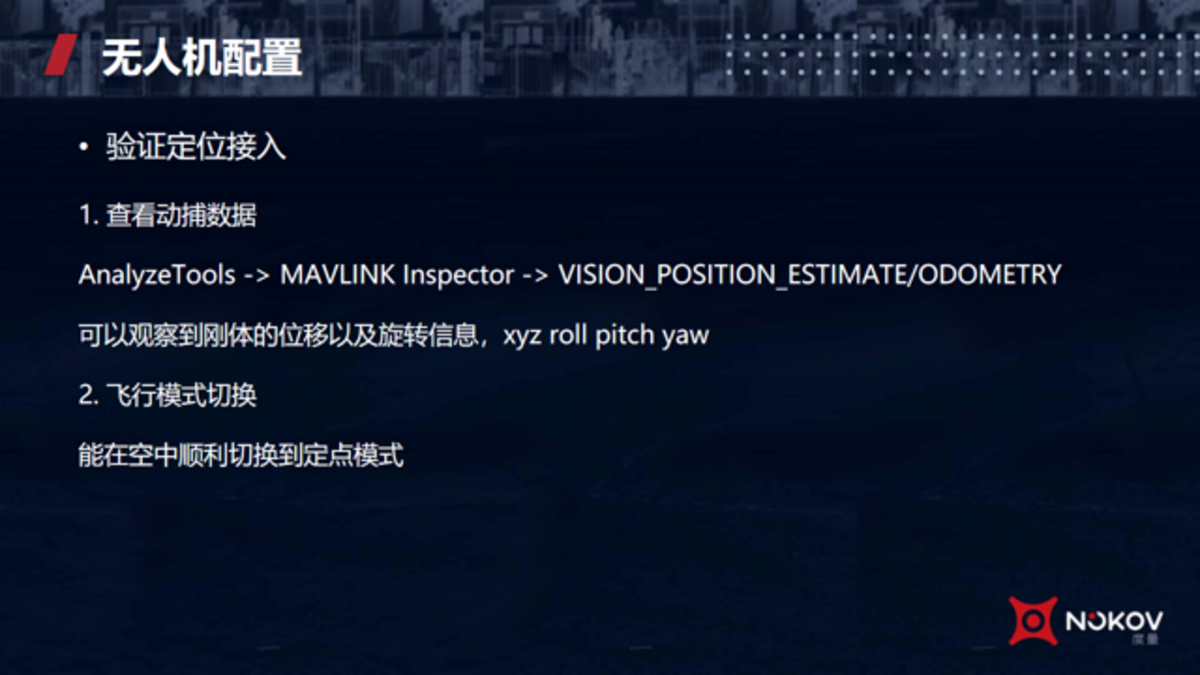
Verify Positioning Access
Verify whether positioning has been successfully accessed. You can perform the following two steps:
- Enable the MAVLink Inspector tool in the ground station software, focusing on monitoring the dynamic response of the following two types of messages:
VISION_POSITION_ESTIMATE message:
Verify whether its "x", "y", "z" three-axis coordinate values maintain synchronous fluctuations with the spatial pose data output by the motion capture system (recommended error threshold ±0.05m)
VISION_POSITION_ODOMETRY message:
Check whether the quaternion attitude parameters (q0-q3) and timestamp fields are continuously updated at a frequency above 20Hz
- Flight mode switching.
Send a mode switching command to the flight controller through the ground station console, and set the flight mode to "Position Hold (Position Hold Mode)".
Ⅲ. Operation Process Demonstration
(Ⅰ) Create Rigid Body
After completing the calibration, place the drone in the middle of the site with the nose facing the positive direction of the x-axis.
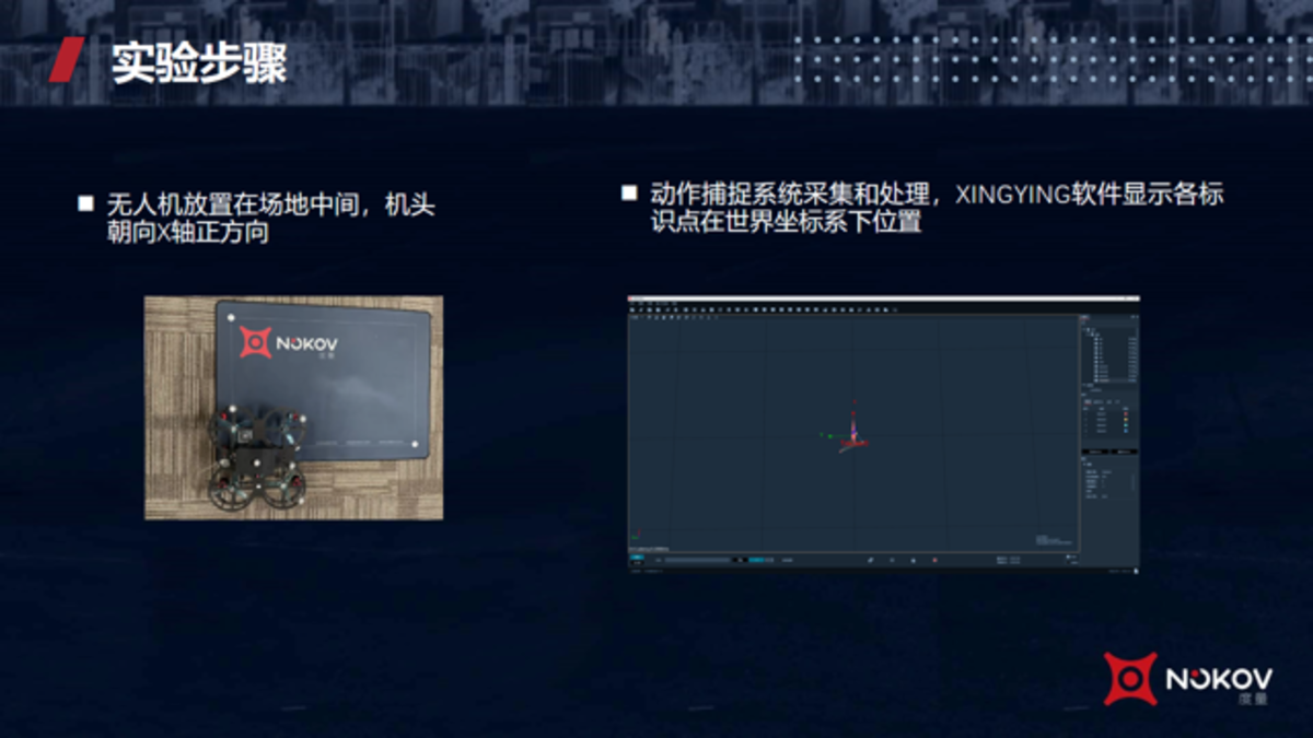
Experiment Steps
Create a rigid body in the XINGYING motion capture software. Steps to create a rigid body:
- First pause playback, then remove tracker, because this is a newly created rigid body
- Click play again, freeze frame, hold Shift and left mouse button, frame select
- Click create rigid body. At this time, tracker0 will pop up on the interface. Then click create, and the rigid body creation is complete.
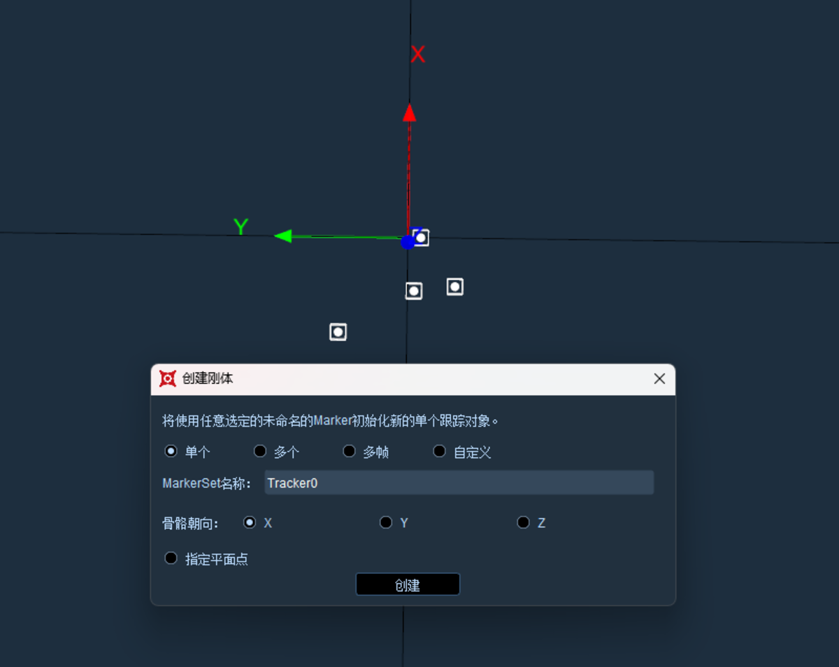
Create Rigid Body
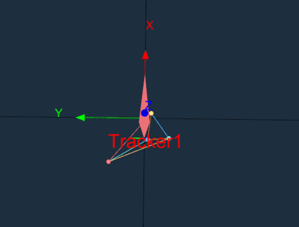
When creating a rigid body, use Tracker1 for naming. You can see the position and orientation of the Tracker1 rigid body.
Tracker1
(Ⅱ) VRPN Broadcast
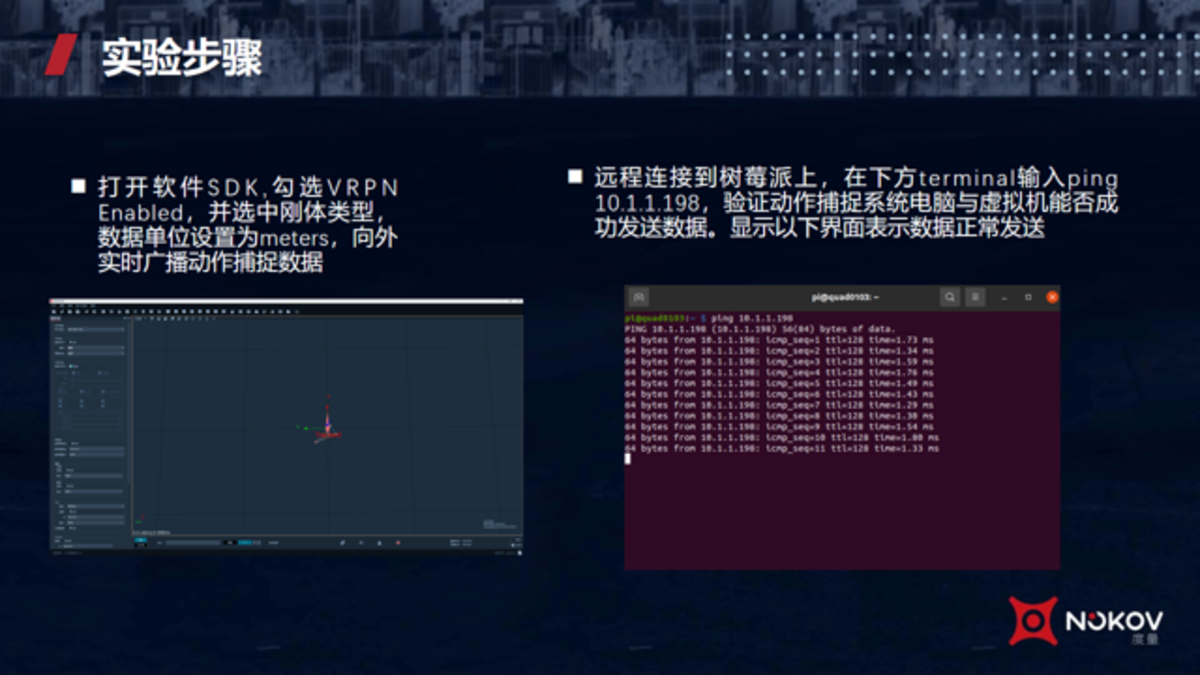
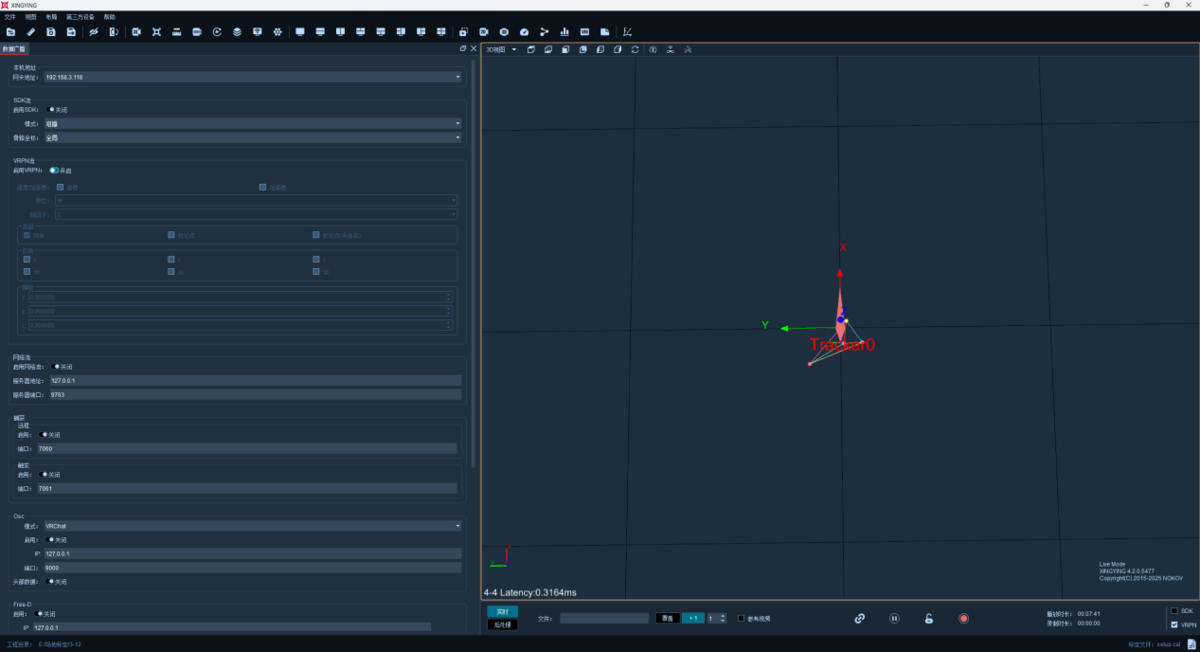
Next, open VRPN broadcast. In the software settings, check the type as Rigid Body, change the unit from the original millimeters to meters, and then click Enable VRPN.
At this time, when we play again, the positioning information of the rigid body has been transmitted through VRPN.
Each network card interface will have VRPN data forwarded, that is, each network card address can receive VRPN data.
Experiment Steps
VRPN Settings
(Ⅲ) Connect Raspberry Pi
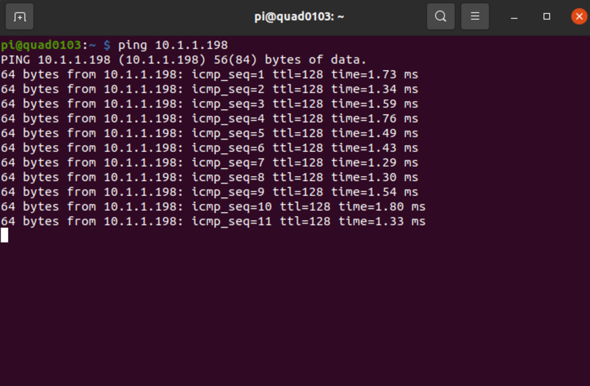
Next, use the ping command on the Raspberry Pi computer to test the network connectivity with the motion capture computer.
ping
Here we can see that the ping command can communicate normally.
Next, complete the previous steps on the Raspberry Pi computer. Because several terminals may be needed, first connect remotely. First start the VRPN client to receive VRPN data.
.png)
vrpn_client_ros
In the terminal, you can use the Tab key to automatically complete.
The IP here should be modified to the IP of the motion capture computer. You can see that the IP of the Raspberry Pi, that is, the onboard computer, is 10.1.1.103.
Run the command, and you can see that VRPN has been connected here.
.png)
vrpn_client_ros
This tracker1 is the tracker1 currently in our corresponding motion capture interface.
.png)
Found new Sender
(Ⅳ) MAV Ros Settings
Next, use MAV Ros.
The ground station address 10.1.1.150 is the IP of the current computer. Run the ground station on the current computer to facilitate observing the drone's status. The default port is 14550.
.png)
roslaunch
Now MavRos has been successfully connected. Some status information of the current drone has been displayed.
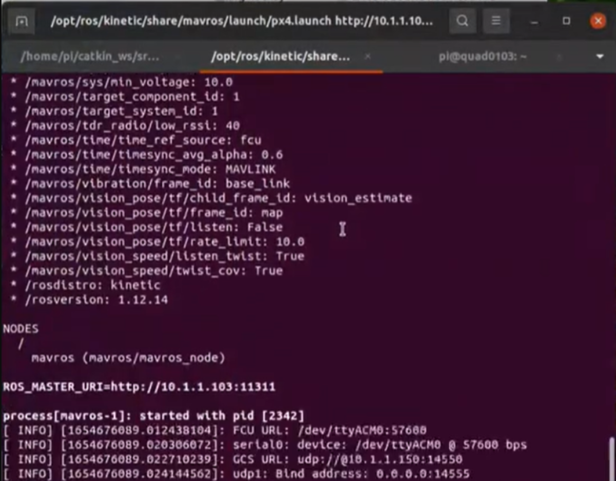
MavRos
(Ⅴ) Topic Forwarding
Perform topic forwarding on the Raspberry Pi.
.png)
Topic Forwarding
Use the RVIZ tool, change the frame to world, then add TF. Here you can see that tracker1 has been displayed.
.png)
rviz
Then add a pose. Change the topic and see vision_pose/pose, then the topic has been forwarded.
.png)
pose
Now the data is dynamically displayed on this graphical tool.
.png)
Experiment Steps
When the drone is lifted up, changes can be seen in real time in both the motion capture software and the current RVIZ tool. Here we can see that the drone is now being held in the air, and the rigid body in the motion capture software has been positioned in the air.
.png)
Motion Capture Rigid Body
Similarly, it can also be displayed in real time in the graphical tool.
.png)
rviz Rigid Body
(Ⅵ) Connect Ground Station
To facilitate viewing the drone's status and issuing control commands, you can use the ground station software on the current computer.
You will find that when our ground station software starts, it will automatically connect to the drone by default.
Here we can see some information about the drone.
.png)
Ground Station Connected to Drone
.png)
Observe Drone Information Through Ground Station
(Ⅶ) Access Verification
Next, verify whether the motion capture positioning system has been successfully accessed.
Without our positioning system, you cannot directly switch to positioning point mode.
.png)
Switch to Position Hold Mode
You can compare here.
Pause the positioning system, and at this time switch to position mode, the switch failed.
Open the positioning data again, and then switch again, this time it can be switched successfully.
(Ⅷ) View Motion Capture Positioning Data
View motion capture positioning data in the analysis tool Mav link inspection panel.
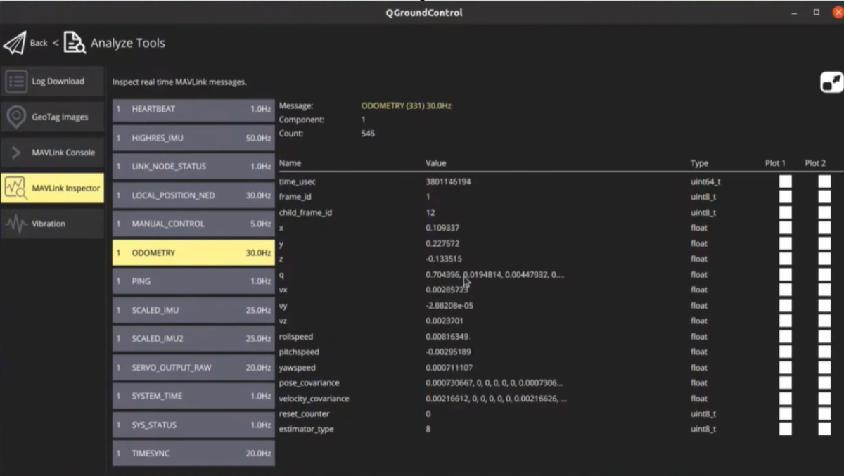
MavLink Inspector
Here is some information transmitted by the current positioning system, including coordinates, orientation, rotation information, and XYZ coordinates, all of which are relatively small values because the drone is currently placed on the ground.
Careful friends will observe that the Z of XYZ is a negative value, while the Z-axis upward in our coordinates should be a positive value. This conversion is done for us by Mavros. For the difference in orientation, you can refer to the official PX4 documentation.
(Ⅸ) Flight Test
After the motion capture positioning system is successful, we can try to unlock and perform a takeoff test.
If you are not familiar with flight controller operation, you can set the takeoff distance to 3ft in the parameters, which is about 90 centimeters in height.
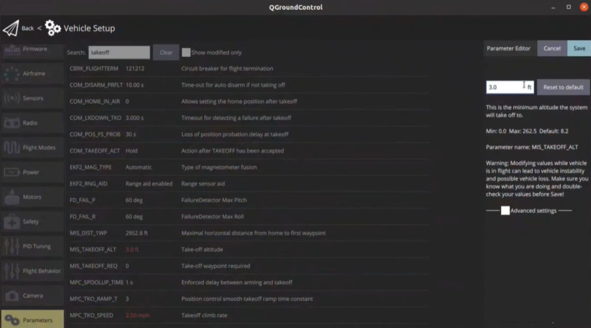
Parameter Settings
Complete demonstration video can be viewed on Bilibili "NOKOV Motion Capture"
https://space.bilibili.com/251016401?spm_id_from=333.337.0.0